CNC Taig Mini Mill |
||||||||||||||||||||||||||||||||||||||||||||||||||||||||||||||||||||||||||||||||||||||||||||||||||||||
Work
|
Figure 1 is a picture of a Taig Micro Mill. This is the CNC version from Taig. The one I bought was CNC ready and I supplied the steppers and driver for it. I bought this after I was forced to move to an apartment due to my job. When I sold my house I put my shop equipment in storage as I obviously couldn't work with it in an apartment. I looked around for a small mill that I could use in an apartment and the choice came down to a Sherline or a Taig. I decided that the Taig would better suit my purpose so I ordered one from Nick Carter. I would likely have never undertaken this, or the CNC router project, with out the support of the CAD_CAM_EDM_DRO mailing list. This list has a huge amount of knowledge present. 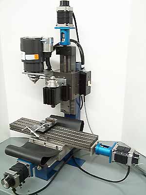 Figure 2 (courtesy of Gecko Drives) is the G201, which I bought from Gecko Drives. It is a single axis drive and will drive up to 7 amps and is a very user friendly drive, if I can figure it out just about anyone can. It's simply a matter of connecting the wires to the terminal blocks on the drive. I bought the G201's from Camtronics 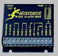 SpecificationsI bought the CNC ready version of Taig's larger mill, the 2019CR. Following are some of the relevant specifications for it. I mounted 210 oz.in. stepper motors while doing the conversion to CNC.
Internal WiringThe internal wiring of the stepper driver is relatively straight forward when using Gecko Drives. Follow the diagram in Figure 3, keeping in mind that what I did is not the only way of doing it (not even necessarily the best way of doing it). Also the power connections are shown daisy chained for ease of drawing, there should be a separate wire for each Gecko. AutoCAD DWG and a larger GIF version of this file are also available. The DWG version would likely be the easiest to use if you have some way of viewing the drawing. A brief description of some of the items will follow.  The AC PLUG is the power supply for the unit. F1 is a 10 amp slo-blo fuse. S1 is the main power switch and S2 is the E-Stop switch. I have that on a long cord so that I can have it near me while working on the mill. The relay that they control is a solid state relay that I had, it allows me to use lighter switches and wiring to the E-Stop switch. I put a spindle plug on the back of my controller. For now it is powered whenever there is power to the drivers. The plan is to eventually put another relay in and control it with software. X1 is the transformer. It is 110 VAC input and 24 VAC 250 VA output. The RECTIFIER is a simple bridge rectifier. C1 is a 20,000 uF 75 VDC capacitor and R1 is bleeder resistor (to slowly bleed the capacitor so it doesn't store energy for a long time after the system is powered down). Each of the Gecko's has a capacitor across it's power supply and the fuse is a 5 amp slo-blo. R2-R5 are the current set resistors, the values for these are calculated as per the instructions that come with the Gecko's. The PARALLEL PORT PINS provide the control from the computer to the Gecko's. The numbers refer to the pin numbers in a DB25 connector. The only thing that is unusual is that I show +5 VDC on pin 25 where it should be ground on a normal parallel port. Read the description further down the page under Computer to Driver Wiring to see how and why this was done. Stepper Motor WiringThe wiring from the stepper driver to each stepper motor is 18 ga. stranded, shielded cable. The 8 wire steppers were connected in parallel. This was done because, as I understand it, you will get more power from the stepper if it is wired in parallel rather than series. Limit/Home Switch WiringInitially I don't have any limit or home switches installed. This means I will have to carefully watch the operation. I do plan on adding home/limit switches once I have the time. The stepper driver is wired for them already so it is only a matter of attaching them to the machine and wring from the driver to the machine. Computer to Driver WiringThe Gecko drives need +5vdc from the computer in addition to the power supplied by the transformer in the controller. There are a couple of ways to do this, I elected to get the power from a port accessible from the back of the computer. Both the game port and the keyboard port have +5v to them. I used a plug that would get the power from pin 1 of the game port but I also made an adapter so I could get the power from pin 4 of a PS2 keyboard port. I did this since I planned on initially using an old laptop, which didn't have a gameport, to run the mill but wanted to be able to easily upgrade to a desktop in the future. A parallel port, which is used for the software to control the drivers connects, with a DB25 connector. Pins 18-25 on the parallel port are all ground lines. Since they are not all required I used pin 25 to carry the +5v from the computer to the controller so that there wouldn't be so many cables and connectors involved. I used a small plastic project box to mount a pc board with terminal strips mounted on it. I cut an old parallel cable in two and connected it inside the box so that all the cables went straight through except the one from pin 25. The wire from pin 25 on the computer side was simply terminated and I connected a wire that went to pin 1 on a game port plug to pin 25 on the parallel cable that went to the controller. The PC's AT Keyboard is connected to external equipment using four wires. In the table I only labeled the pins I used, or planned to use in the future, on the different connectors on the parallel port (DB25), gameport (DB15), and the keyboard (5 Pin DIN male plug or PS/2 plug). These pinouts are for CNCPro as that is the software I'm using to control the mill. I wired the driver for a fourth axis (A) even though I don't currently have one. The plan is to wire for it and then, if I need it, I simply need to get a fourth Gecko 201 to install in the driver.
|
|||||||||||||||||||||||||||||||||||||||||||||||||||||||||||||||||||||||||||||||||||||||||||||||||||||
|
|